In the Zone - Cabling Design for today's Intelligent Buildings
In the Zone
 Intelligent Buildings have changed the landscape of low-voltage infrastructure layout. One of the biggest changes is selecting the proper cable and topology to deliver network data and power (PoE) to devices, which had previously run on many different disparate cabling types and automation systems. These include security cameras, access control, wireless access points, HVAC, lighting and many more. Location of these devices vary greatly since they do not attach to typical telecommunications outlets installed 15” above the floor. These applications are fixed in ceilings, on walls, by doors, as well as outdoors in garages and parking lots. Gaining attention to connecting IP cabling to these devices is to employ a flexible zone cabling layout.
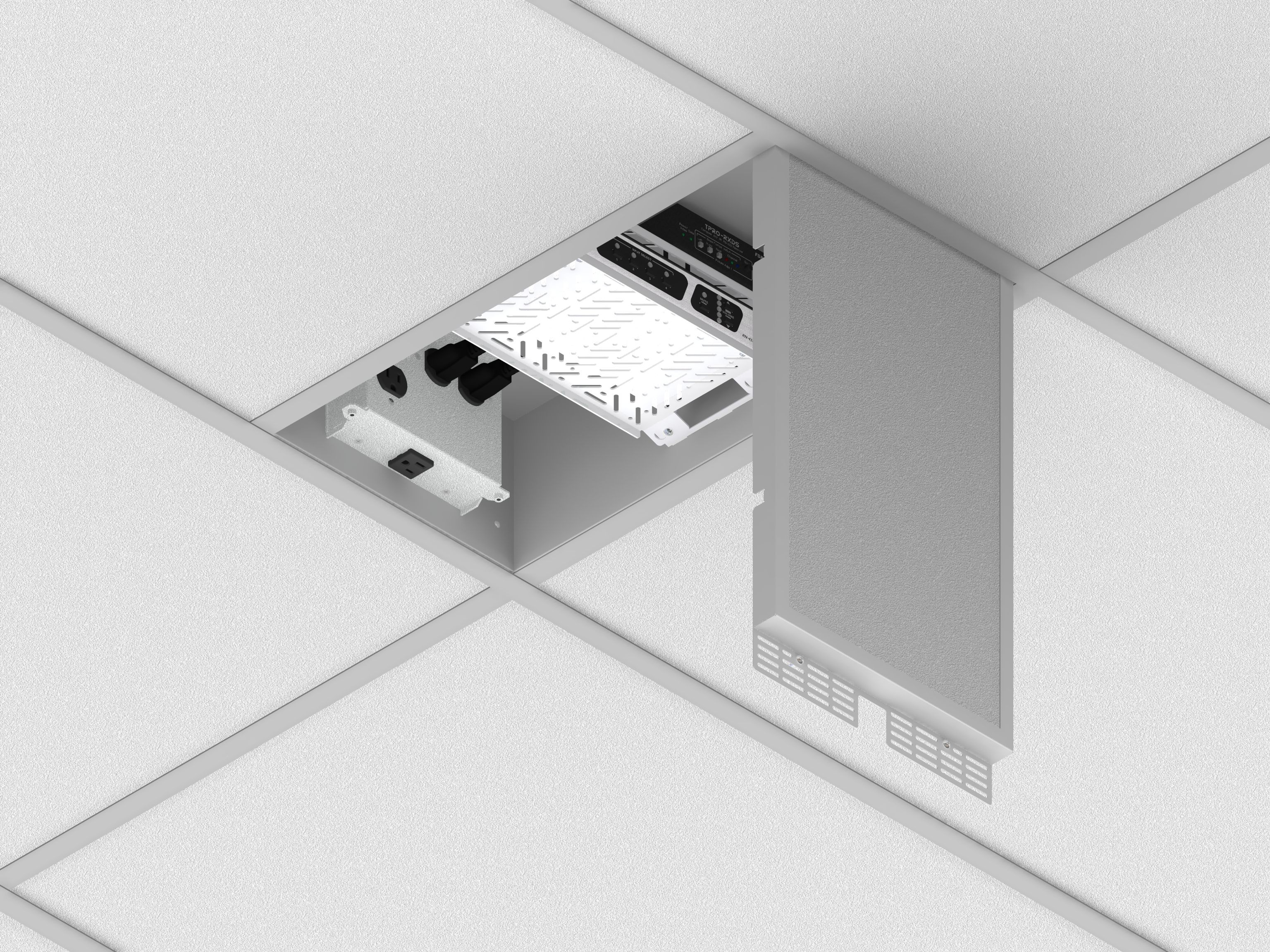
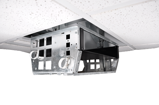
 A CB Series of zone enclosures from FSR Inc. are designed to house both active and passive equipment for intelligent building applications. Zone cabling was originally introduced to provide flexibility for open office space. But with the growth of PoE and converged applications onto the data network, zone cabling expanded its widespread use. A zone cabling design consists of an intermediate connection point, referred to as a Horizontal Connection/Consolidation Point (HCP) between the Telecommunications Room (TR) and the end devices. Cables are pulled and terminated into the HCP, also called a zone enclosure, or ceiling box. From the cross connection in the zone enclosure, additional horizontal cables are pulled to the outlets or connected directly to the device through a modular plug terminated link (MPTL).
The major benefit of a zone cabling design is that it provides easy-to-manage cabling between the TR and the devices, without having to homerun cable from all the way back to the TR. A zone layout also reduces labor and material costs during reconfiguration because the cabling from the TR to the HCP stays intact, especially when adding future devices that will only require cable or patch cords from the HCP.
Zone Cabling Guidelines
There are two standards that provide well-defined guidelines for the design, planning and installation of a zone cabling layout as an integral part of an intelligent building infrastructure — TIA-862-B-2016 Structured Cabling Infrastructure Standard for Intelligent Building Systems and ANSI/BICSI-007-2020 standard, Information Communication Technology Design and Implementation Practices for Intelligent Buildings and Premises. Together these two documents complement each other to provide cabling installation planning but may vary in some of the recommendations.
For twisted-pair copper cabling, both TIA and BICSI recommend Category 6A for new installations or Category 6 at minimum in an existing building or as a retrofit. In addition, BICSI also recognizes that in existing installations of intelligent building systems, the use of non-recognized horizontal cabling shall be allowed if the following conditions are met: use of non-recognized cabling does not violate current Code or AHJ requirements; the need for cabling is a result from the movement, expansion, or other alterations to an existing system; or the non-recognized cabling meets or exceeds the performance of the existing cabling in use by the specific system.
TIA provides guidelines for cabling types, pathways, terminations and installation best practices. A zone enclosure or HCP is defined by TIA to house one or more of the following: a) a consolidation ; b) a horizontal connection point; or, c) intelligent building system outlet. For twisted-pair cabling, in order to reduce the effect of multiple connections in close proximity on NEXT loss and return loss, the HCP should be located at least 15 m (49 ft) from the TR (or “Distributor”) that houses the active equipment. When cross-connections are used at the HCP, an equipment outlet shall not be installed as part of Cabling Subsystem 1 to ensure that the cabling channel contains no more than four connections. The zone enclosure should be sized to accommodate immediate requirements and long-term growth but not more than 96 connections.
The BICSI standard leverages the requirements by TIA but delves more granular into the best practices for planning spaces, topology and media selection for the additional building applications. The revised BICSI-007-2020 has expanded the section on design considerations for zone enclosures to include more options and topologies for horizontal cabling and contains diagrams and layouts that depict examples of a star topology (point-to-point), different coverage area patterns, and tree topology.
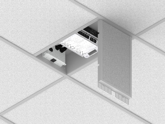
Although TIA recognizes zone enclosures as only housing passive cross connections (or interconnections) for data or building devices, BICSI’s 007-2020 version states, “Unlike a consolidation point, an HCP may be either active or passive.” Allowing active equipment, such as PoE extenders, midspan injectors, AC outlets, fans or switches within the HCP expands the design of the zone boxes. Spare capacity for future expansion is considered when determining the size of the HCP. Manufacturers of ceiling boxes are now offering different configurations, sizes and features. (See photo for a ceiling box with electrical connections and accommodation for both patching fields and active components)
Zoning Out
A zone cabling horizontal channel distance is limited by TIA to 100m for twisted pair cabling from the equipment in the TR to the device itself, including patch cords. This means that if the HCP is located at least 15m from the TR, that the end device can not run further than 85m from the zone enclosure (including the patching field) (See Figure 1). Since most of building devices are beyond 100m, there are options – add PoE extenders, which would require AC power for the active components, or use a hybrid fiber/copper cable which would include employing media converters and PoE extenders and AC power, which greatly increases the material and installation costs, or simply specify the long-distance GameChanger Cable™. The patented 22 AWG GameChanger cable more than doubles the distance of a Category 6 or 6A cable (unshielded or shielded) out to 260m (850 ft.) from the TR to the device if the zone box only houses a cross connection. If active PoE midspans or digital building PoE switches are installed in the HCP, then the GameChanger cable can run out to 260m from that point which drastically extends the total horizontal cable run. (See Figure 2).
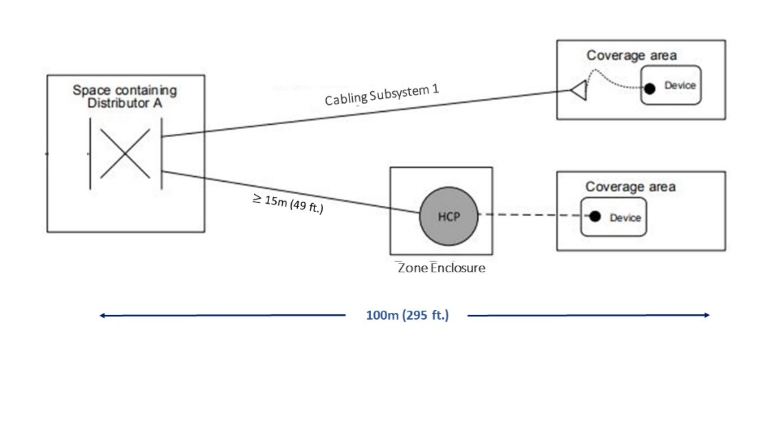 Figure 1: TIA-862B-2016 - Example of a Cabling Subsystem 1 using a star topology to coverage areas
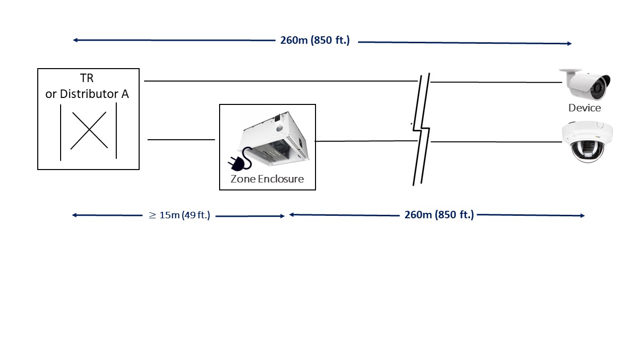 Figure 2: GameChanger Cable extends the cable channel distance to 260m/850 ft. without zone cabling or at least 275m/899 ft with an HCP containing active equipment.
