
GameChanger®
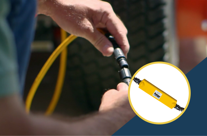
The original extended-distance CAT6 with 2.5 Gb/s Ethernet and 100W PoE over 200 meters.
It earned its name because it changed the game: The Paige GameChanger® Cable. Powered by more than 65 years of experience, we engineered a unique solution that paved the way for others to follow – the first extended-distance CAT6. The GameChanger® extends over 200 meters with 2.5 Gb/s Ethernet and 100W PoE. Pulling and terminating like a CAT6 with no need for boosters, extenders, transceivers, or extra IDFs, it has fewer points of failure, works faster, and makes for less expensive installs.
The original extended-distance CAT6 with 2.5 Gb/s Ethernet and 100W PoE over 200 meters.
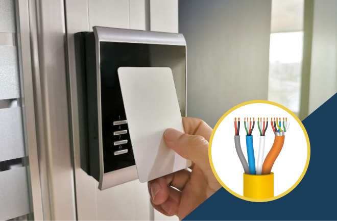
Advanced functionality and an OSDP protocol that offers the ultimate level of security for your access control system.
Get better protection with an easy-to-use, monitored solution that connects to any existing security system.
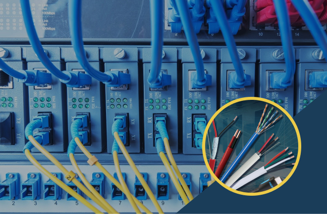
A comprehensive offering of wire and cable for Video, Voice, Data, Fire, Sound and Security.

Working with us doesn't mean just ordering wire, it means creating a partnership with a trusted advisor. Let our experts help with any project issues or needs.
We believe innovation doesn't mean telling our customers what they need. It means listening to the issues they're experiencing, and then engineering the perfect solution.

With us, it’s personal. If you need us, we’re there. Chat with our wire and cable experts 24/7 or call your dedicated account representative.

Excellence and Responsibility
Paige has earned ISO 9001:2015 certification for its factories in Columbus, NE and Silao, Mexico. We are dedicated to ensuring customer satisfaction and continual improvement, while embracing sustainability practices.
You can view our latest ISO Certificates here.