
Right Sizing Your Pathways—From Tray to Conduit
Right Sizing Your Pathways—From Tray to Conduit
When it comes to pathways for communications cabling to get from one place to another, industry codes have specific requirements on the types and amounts of cables that can be deployed. For example, the National Electric Code (NEC®) requires that communications cables such as Category 6 and Category 6A be separated from any electric light, power, Class 1, non-power-limited fire alarm, or medium power circuits. For communications cables carrying power such as PoE, the code also specifies how many cables can be placed in a bundle based on the wire gauge, temperature rating of the cable, and ampacities of each conductor.
There are also plenty of specifics around pathway sizing—some of which are required by code and some of which are recommended by industry cabling standards. (Check out our blog on the difference between codes and standards to understand what’s mandatory and what’s not.) In fact, there is an entire TIA-569 standard that covers just pathways and spaces. Within cabling standards and codes there is one factor that is key to designing and deploying a network cable plant—fill ratios. Let’s take a closer look.
The 25% Design Rule
Properly sizing pathways in the early design stage is critical to the performance and future proofing of a cable plant—it’s not exactly something that is feasible to change once a building is constructed. Sizing therefore must include projected future as well as any immediate requirements.
In commercial buildings, communications cables typically traverse horizontal spaces via cable tray. For cable tray, TIA-569 recommends planning for an initial maximum calculated fill ratio of just 25%. While this doesn’t sound like the most efficient use of space, buildings are dynamic and ever-evolving technology means that more cables are likely to be added in the future. Furthermore, the 25% rule is just for design purposes. Per the NEC, the actual maximum fill ratio of any cable tray is 50%. TIA recommends a maximum 40% fill ratio based on the cross-sectional area of the cable and the tray area (width X depth).
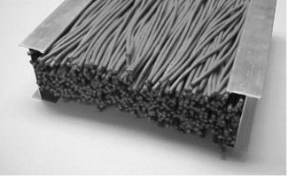
While you still may be shaking your head and wondering why you can only fill cable tray to a maximum of 50%, the fact is that due to empty spaces between the surface of the cables, cable tray will be nearly completely filled at 50%. The image below from the TIA-569 standard of a cable tray section with 0.22-inch diameter cables at 50% fill demonstrates this quite clearly.
When in Conduit
The bulk of a cable plant will reside in cable tray since it’s inexpensive from a labor and material standpoint, offers greater design flexibility, and providers easier access for inspection and moves, adds, and changes compared to conduit. But the fact is that there may be certain scenarios and environments where conduit is required to provide physical protection or shielding from electromagnetic interference (EMI). According to TIA-569, conduit should be used when it is required by code and considered for when cabling and outlet locations are permanent and when special mechanical protection is required.
There are two primary types of conduits—rigid and electrical metallic tubing (EMT). Rigid conduit is very thick and often coated to provide corrosion resistance. It is typically used to encase cables underground and in very harsh environments. EMT is a lightweight steel conduit that provides good physical protection in most locations, including buried in concrete.
Just like with cable tray, it’s important to properly size conduit and limit conduit fill. The size of the conduit is based on the planned diameter of the cable and the maximum pull tension that can be applied to the cable when it’s pulled through the conduit. Even if conduit is used for permanent cable installation in a space where the need to later inspect or add more cables would be unlikely (e.g., in concrete), conduit fill is still limited by code. In fact, the maximum fill ratio for conduit per the NEC is 53% for one cable, 31% for two cables, and 40% for three or more cables. Due to the nature of friction when pulling cable through conduit, the number of cables needs to be reduced if there are more than two 90-degree bends in the conduit. Note however that avoiding any 90-degree bends in conduit is recommended.
Valuable Fill Charts
While the NEC tells you what the maximum fill ratio is for conduit and calculations are fairly straightforward, they can be time consuming and frankly annoying – you need to know how many cables you have and the cross-sectional area of the cables, which can vary from one manufacturer to another. Plus, some manufacturers may recommend reducing the number of cables or use larger conduit for longer runs and the NEC requirements do not take into account every factor that could affect conduit fill. For example, attenuation of some category cables can increase when installed in metal conduit.
Leading manufacturers provide conduit fill charts based on their specific cables to simplify the process of sizing conduit and calculating how many cables can be deployed within a given conduit. Paige is no exception. We have a cable conduit fill chart for our GameChanger® cables by part number and rating (e.g., riser, plenum, OSP, and OSP shielded) that tells you exactly how many cables you can fit into various sizes of rigid and EMT conduit based on the NEC requirements.
By combining innovative wire and cable solutions with a service-focused approach, Paige has become the go-to provider for application-driven products for more than 60 years. With an operating presence in more than 100 countries and seven North American locations, we have the reach to handle the most complex jobs and the expertise to customize any order to our customers’ exact needs.
If you have any questions about conduit fill requirements for any of our cables, we’re here to help. Chat with us online at www.paigeconnected.com.
